Electricity is an important topic in Class 10 Science, and it's essential to have a good understanding of the concepts to do well in exams. These simplified notes cover the key topics in electricity, including electric current, circuits, Ohm's law, Series connenction, Parallel connection, Heating effect, and Power making it easy to revise and prepare for your exams.
| Subject | Science (Physics) |
| Class | 10 |
| Board | CBSE |
| Chapter No. | 11 |
| Chapter Name | Electricity |
| Type | Notes |
| Session | 2025-26 |
Electricity Class 10 Notes
Table of Contents
Electric Current and Circuit
- If the electric charge flows through a conductor, we say that there is an electric current in the conductor.
- Electric current is expressed by the amount of charge flowing through a particular area in unit time. In other words, it is the rate of flow of electric charges.
- Conventionally, in an electric circuit, the direction of electric current is taken as opposite to the direction of the flow of electrons, which are negative charges.
- A continuous and closed path of an electric current is called an electric circuit.
If, Charge = Q, time = t, current = I, then
- I = Q/t
SI unit of Electric Charge: coulomb (C)
- 1 C ≈ 6 x 10¹⁸ electrons
- 1 electron = 1.6 x 10⁻¹⁹ C charge
SI unit of Electric Current: ampere (A)
- One ampere is constituted by the flow of one coulomb of charge per second.
- Smaller quantities of current are expressed in milliamperes (mA) or in microamperes (μA)
- 1mA = 10-3 A
- 1μA = 10-6 A
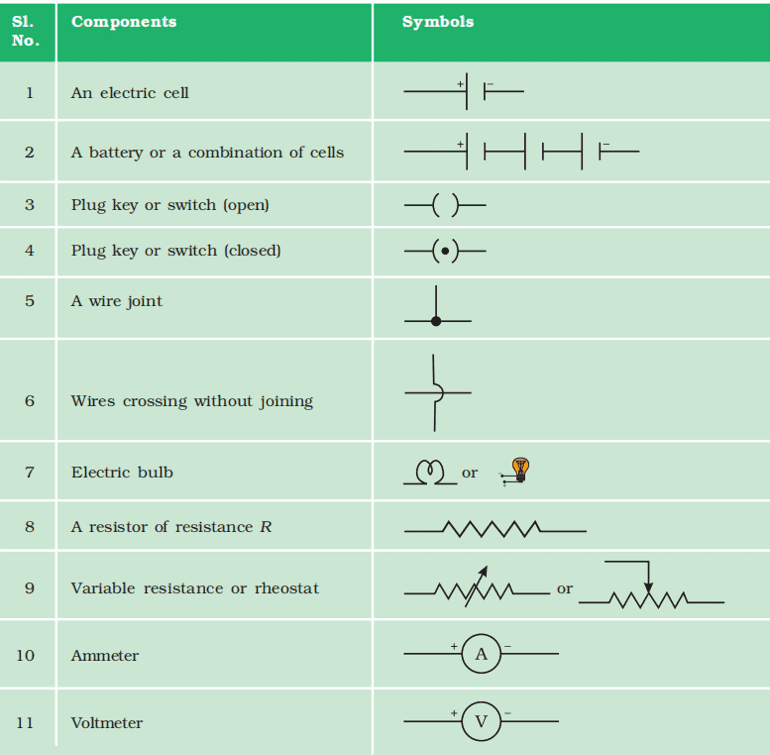
Ammeter:
- An instrument called an ammeter measures electric current in a circuit.
- It is always connected in series in a circuit through which the current is to be measured.
Schematic Diagram of an Electric Circuit:
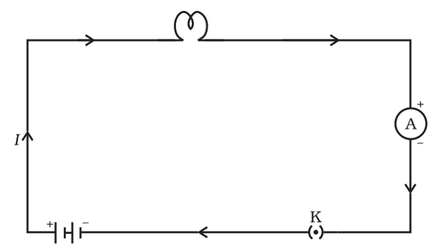
Note that the electric current flows in the circuit from the positive terminal of the cell to the negative terminal of the cell through the bulb and ammeter.
Electric Potential and Potential Difference
The work done to move a unit charge from one point to the other is called the potential difference between two points.
- V = W/Q
SI unit of Electric Potential Difference: volt (V)
One volt is the potential difference between two points in a current carrying conductor when 1 joule of work is done to move a charge of 1 coulomb from one point to the other.
Voltmeter:
- The potential difference is measured by means of an instrument called the voltmeter.
- The voltmeter is always connected in parallel across the points between which the potential difference is to be measured.
| Voltmeter | Ammeter |
| i. It is used to measure the potential difference across two points in an electric circuit. | i. It is used to measure electric current in an electric circuit. |
| ii. Its resistance is very high. | ii. Its resistance is very low. |
| iii. It is connected in parallel in an electric circuit. | iii. It is connected in series in an electric circuit. |
Circuit Diagram
Ohm's Law
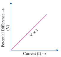
Ohm’s Law: Potential difference across the two points of a metallic conductor is directly proportional to the current passing through the circuit provided that temperature remains constant.
Mathematical expression of Ohm’s Law:
V ∝ I
⇒ V = IR
R is a constant called resistance for a given metal.
V-I graph for Ohm’s Law:
Resistance: It is the property of a conductor to resist the flow of charges through it.
Its SI unit is ohm (Ω).
1 ohm: If the potential difference across the two ends of a conductor is 1 V and the current through it is 1 A, then the resistance R, of the conductor is 1 Ω.
| Good Conductor | A component of a given size that offers a low resistance is a good conductor. |
| Resistor | A conductor having some appreciable resistance is called a resistor. |
| Poor Conductor | A component of identical size that offers a higher resistance is a poor conductor. |
| Insulator | An insulator of the same size offers even higher resistance. |
Factors on which the Resistance of a Conductor Depends
Resistance of a uniform metallic conductor is:
- Directly proportional to the length of the conductor (l).
- Inversely proportional to the area of cross-section (A).
- Directly proportional to the temperature.
- Depend on the nature of the material (ρ).
R = ρl/A
Resistivity:
- ρ (rho) is called the electrical resistivity of the material.
- Its SI unit is Ω m.
- It is a characteristic property of the material.
- The metals and alloys have very low resistivity in the range of 10–8 Ω m to 10–6 Ω m. They are good conductors of electricity.
- Insulators like rubber and glass have resistivity of the order of 1012 to 1017 Ω m.
- Both the resistance and resistivity of a material vary with temperature.
- The resistivity of an alloy is generally higher than that of its constituent metals.
- Alloys do not oxidise (burn) readily at high temperatures. For this reason, they are commonly used in electrical heating devices, like electric iron, toasters etc.
- Tungsten is used almost exclusively for filaments of electric bulbs.
- Copper and aluminium are generally used for electrical transmission lines.
Resistance of a System of Resistors
1. Resistors in Series
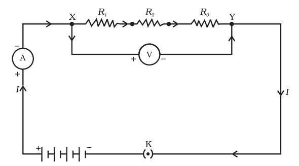
- In a series combination of resistors the current is the same in every part of the circuit or the same current through each resistor.
- The total potential difference across a combination of resistors in series is equal to the sum of potential difference across the individual resistors.
- V = V1 + V2 + V3
- Equivalent resistance (Rs) of three resistors in series (R1, R2, and R3) = Sum of R1, R2, and R3
- Rs = R1 + R2 + R3
2. Resistors in Parallel
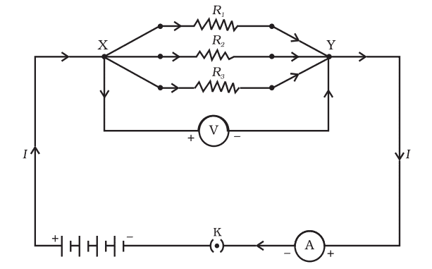
- The total current I, is equal to the sum of the separate currents through each branch of the combination.
- I = I1 + I2 + I3
- Potential difference is same across each resistor.
- Equivalent resistance of three resistors in parallel (R1, R2, and R3) = Rp
- 1/Rp = 1/R1 + 1/R2 + 1/R3
Advantages of parallel combination over series combination:
- If one appliance stops working or goes out of order, then all other appliances keep on working.
- All appliances can be operated at the same voltage as the electric supply.
- Different appliances have different requirements of current. This cannot be satisfied in series as the current remains the same in series.
- The total resistance in a parallel circuit is decreased.
- All devices can be operated independently with separate switches.
Heating Effect of Electric Current
W (work done/hear/electrical energy) = QV = VIt = I2Rt = V2t/R
Joule's law of heating: The law implies that heat produced in a resistor is
- directly proportional to the square of current for a given resistance,
- directly proportional to resistance for a given current,
- directly proportional to the time for which the current flows through the resistor.
Practical Applications of Heating Effect of Electric Current
The electric laundry iron, electric toaster, electric oven, electric kettle and electric heater are some of the familiar devices based on Joule’s heating.
Electric Bulb:
- The electric heating is also used to produce light, as in an electric bulb.
- A strong metal with high melting point such as tungsten (melting point 3380°C) is used for making bulb filaments.
- The bulbs are usually filled with chemically inactive nitrogen and argon gases to prolong the life of filament.
Fuse:
- It protects circuits and appliances by stopping the flow of any unduly high electric current.
- The fuse is placed in series with the device.
- If a current larger than the specified value flows through the circuit, the temperature of the fuse wire increases. This melts the fuse wire and breaks the circuit.
- For an electric iron that consumes 1 kW electric power when operated at 220 V, a current of (1000/220) A, that is, 4.54 A will flow in the circuit. In this case, a 5 A fuse must be used.
Electric Power
- The rate at which electric energy is dissipated or consumed in an electric circuit is called electric power.
- P = VI = I2R (use this formula in series connection) = V2/R (use this formula in parallel connection)
- The SI unit of electric power is watt (W).
- 1 W is the power consumed by a device that carries 1 A of current when operated at a potential difference of 1 V.
- The commercial unit of electric energy is kilowatt hour (kW h), commonly known as ‘unit’.
- 1kWh = 1000 Wh = 1000 x 60 x 60 Ws = 3600000 ws = 3.6 x 10⁶ joule
| Must Also Prepare this: Electricity Class 10 Important Questions and Answers Electricity Class 10 MCQ Test |

Hope you liked the Notes on Electricity Class 10. Please share this with your friends and do comment if you have any doubts/suggestions to share.
Related posts:
 Class 10
Print Culture and the Modern World Class 10: Important Questions, Easy Answers
Acids, Bases and Salts Class 10 Important Questions and Answers
Federalism Class 10 Most Important Questions and Answers
Manufacturing Industries: Demystified with Class 10 Questions and Answers
Class 10
Print Culture and the Modern World Class 10: Important Questions, Easy Answers
Acids, Bases and Salts Class 10 Important Questions and Answers
Federalism Class 10 Most Important Questions and Answers
Manufacturing Industries: Demystified with Class 10 Questions and Answers
 CBSE Class 10 Maths Sample Paper: Exam Setup, Question Types & Solutions
Life Processes Class 10 Notes: Simplified and Easy to Understand
The Thief’s Story Class 10: Top Questions and Answers for Exam Preparation
CBSE Class 10 Maths Sample Paper: Exam Setup, Question Types & Solutions
Life Processes Class 10 Notes: Simplified and Easy to Understand
The Thief’s Story Class 10: Top Questions and Answers for Exam Preparation
The notes were really very helpful! Thank you so much!
Thx^^
Mcq
Sir your method to easy to understand.